Parallel Connection and Redundancy of Power Supplies – What Is the Difference?

December 1, 2022
You are in need of a higher total power for your system or machine, or want to ensure a reliable power supply? Common solutions include the parallel connection or establishing a redundant power supply system. In this blog post, you will learn more about the definition, the differences and the correct use of both system types.
Maximizing utilization vs. minimizing downtime
By connecting two or more power supply units of the same type in parallel, they share the supply of a system or machine. Collectively supplying power thus enables a higher total power.
A redundant power supply system, on the other hand, increases the reliability of the system or machine. Here, additional power supply units are installed in the machine or system as a reserve. In case one of the units fails, the remaining power supply units maintain the system operation. Redundancy modules protect against back feeding into a possibly short-circuited power supply output.
More total power – How does a parallel connection work?
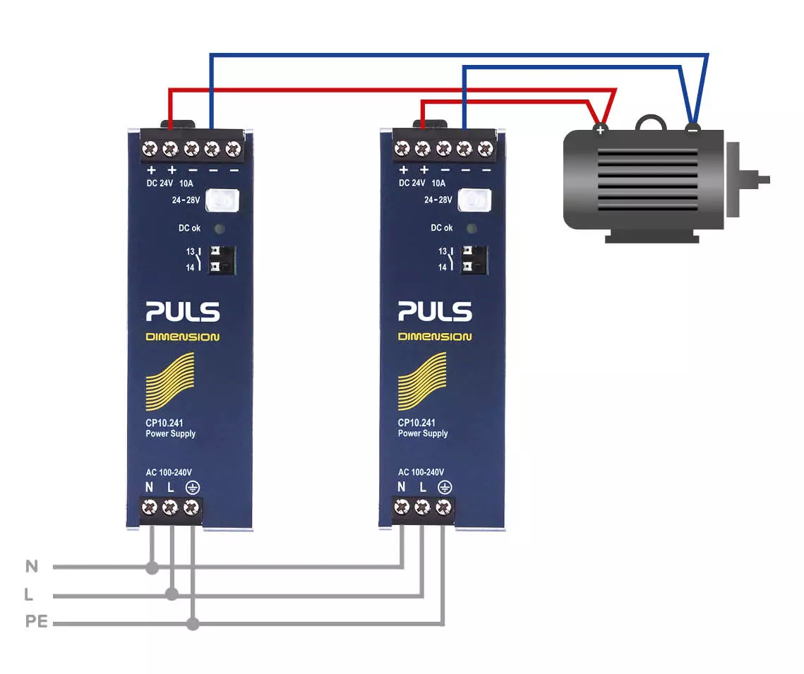
By using power supplies in parallel, the load current required by the system or machine is supplied jointly by several power supply units.
What types of parallel connection are there for power supplies?
In general, you can classify power supplies, that can to be connected in parallel, into two groups: power supplies with and without load sharing.
In the case of power supplies without load sharing, it is not possible to ensure a balanced current distribution. This can lead to overload and overheating of a power supply, which can develop into a failure of the device.
Figure 1: Structure of a simple parallel connection
Power supply units with load sharing, on the other hand, ensure a balanced current distribution. This prevents one or more devices from being overloaded. A distinction can be made here between active and passive load sharing.
In active load sharing, connected control circuits ensure exact synchronization of the output voltages among the power supplies. However, this is very complex and susceptible to interference.
If a 100% balanced distribution is not fundamental, passive load sharing can be used. Here, the output voltages are set to be as congruent as possible.
As the output current increases (from no-load voltage to full load), the output voltage is reduced (inclined characteristic curve). If one power supply unit falls below the output voltage of the other, the other unit participates in the current supply (see figure 2).
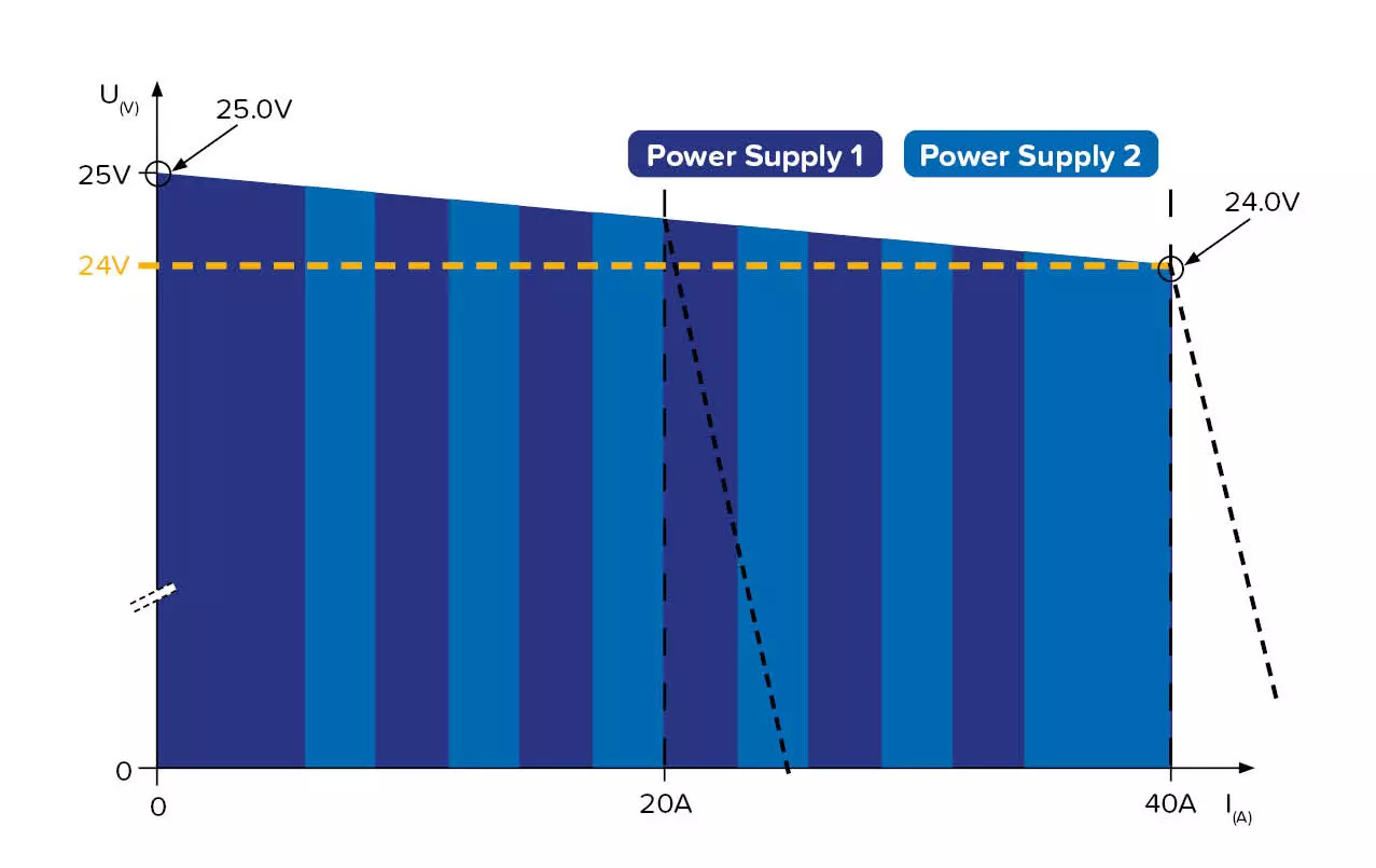
Figure 2: Passive parallel circuit with inclined characteristic curve
The more congruent the power supplies are set, the more balanced is the current distribution – for example, in a 40 to 60% ratio. However, a totally balanced 50:50 distribution will not be achieved here.
Passive load sharing is reliable and inexpensive. For many systems and machines, this mode of operation is absolutely sufficient. PULS, therefore, specializes in passive load sharing for most power supply units with paralleling functionality.
How do I set up a parallel connection correctly?
To achieve a balanced load between the power supply units connected in parallel, the output voltages must be set as precisely as possible to the same value. Each power supply manufacturer designs its output circuit differently. Therefore, it is recommended to use identical power supply units of the same brand. This enables reliable adjustments and prevents unforeseen problems during operation.
To minimize the risk of overheating devices, power supplies must be arranged next to each other and not mounted on top of each other. Take into account the specifications on the minimum spacing between the devices according to the installation manuals.
Higher availability – What is a redundant power supply system?
In a redundant power supply system, more power supplies are used than are actually required to supply the load. The units share the total load among themselves (= paralleling). If one of them fails, the total load is carried by the remaining power supply units. Should the defective power supply unit have a short circuit in the process, a protects it from being fed back into the short circuit.
This reliable power supply thus ensures the high availability of the machine or system. Redundant power supply systems are used especially when a power supply failure is intolerable.
One application is in the automotive industry, where the cost of a production shutdown far exceeds the cost of setting up a redundant power supply system from the beginning. Another example is the food industry: Due to hygiene regulations, systems that have come to a standstill must be completely cleaned before they can be put back into operation. This maintenance is time-consuming and cost-intensive and can be prevented by a redundancy system.
What types of redundancy are there?
There are several redundant systems to choose from. Some of the most commonly used include the 1+1 and N+1 redundancy.
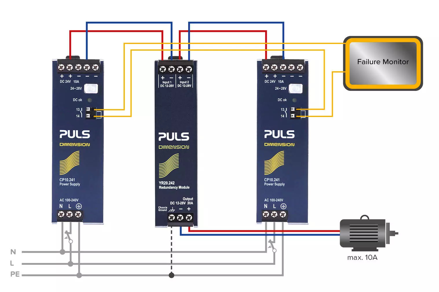
The 1+1 redundancy requires three components: two identical power supply units and one redundancy module.
The power supplies share the load current among themselves. If one of the two fails, the other takes over 100% of the load to be supplied. For a 10A load current, two 10A power supply units are needed.
You could set up this 1+1 redundancy system with two CP10.241 power supply units and one YR20.242 redundancy module.
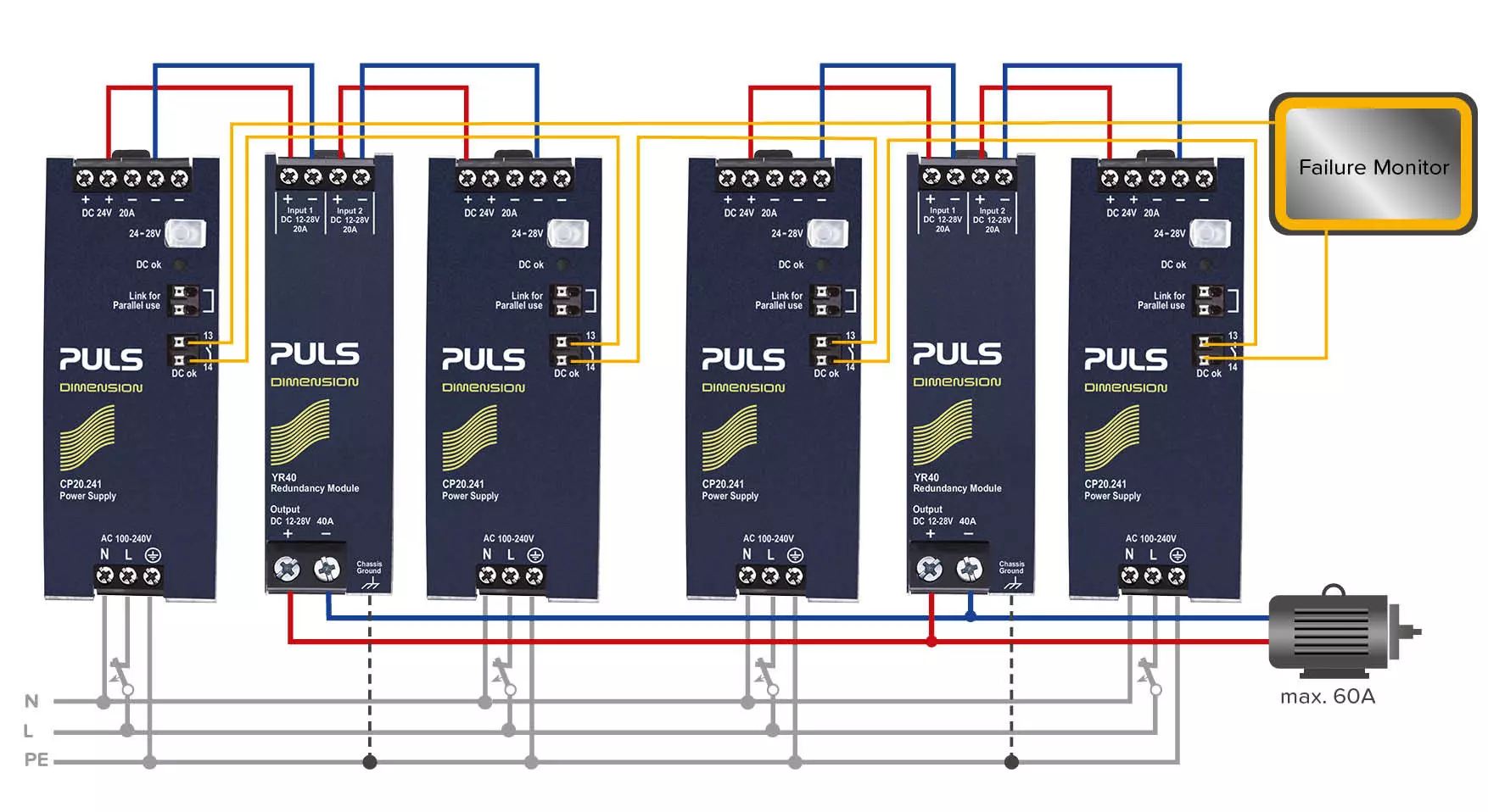
With a N+1 redundancy, one power supply is installed as a reserve in addition to the required power supply units (N = number).
For a total load of 60A, for example, three 20A power supply units are required. In this case, however, four 20A units share the load (at 15A each). If one fails, the three remaining power supplies can still provide the total load.
You could set up this N+1 redundancy system with four CP20.241 power supply units and two YR40.241 redundancy modules.
In a redundant power supply system you must also pay attention to the rules of parallel connection, mentioned before.
With the N+1 redundancy, you should only use power supply units which are allowed to be used in parallel. As for the 1+1 redundancy, the total load can be supplied by a single unit, which is why a single unit is never overloaded. For this reason, power supply units that are not explicitly marked as parallel-capable can also be used for the 1+1 redundancy.
What should you pay attention to when using redundancy?
For the redundant power supply system to serve its purpose, each power supply should be connected to a different AC source. This prevents a total failure in the event of a fault on the input side. However, this separate AC supply is often difficult to implement in the control cabinet.
A redundant system should also provide a means of monitoring the power supply units. In the event of a fault, an external signal sends an alarm to the PLC which informs the maintenance team. The technician can then quickly replace the faulty power supply unit without any downtime. This seamless monitoring of the units enables smooth maintenance work.
Conclusion
A parallel connection of power supplies is primarily used to increase the total power. Here, power supply units jointly provide the load required to operate a machine or system.
A redundant power supply system focuses on the reliability of the power supply. In this case, several power supply units jointly supply a machine or system with power as well. In contrast to parallel connection, the total load in a redundant system can be provided without interruption even, if one power supply unit fails. To achieve this, more power supply units are used than are actually required for the load current. Redundancy modules protect against backfeeding into a possibly short-circuited power supply output. This solution is used when downtime must be prevented.
Please do not hesitate to contact our team of PULS Application Engineers (PAC) for further information. Please use the or get in touch with your contact person directly.

