Achieving Matrimony Between Machine Vision and Motion Control in Lab Automation – A Case Study
September 8, 2022
Written by Krystie Johnston
Introduction
Industrial robots continue to gain popularity as companies realize their potential for time and cost savings. They are prevalent in the automotive, packaging, and food and beverage industries, and are showing up in the medical and life sciences industries as well.
These robots are programmed to complete a standard function or task, are valued for their reliability and repeatability, and as their technology develops, the tasks that they are doing are evolving. Complex motion control systems, incredibly accurate machine vision, and the progressing matrimony between them creates infinite opportunities to handle tasks that would not have been imaginable a few generations ago.
As technological advancements become common-place and affordable, more industries look to implement motion control and machine vision systems to automate tasks that may be menial and time consuming. This not only improves accuracy and efficiency in certain areas, but elevates people so they can concentrate on higher-level responsibilities.
Many industries can benefit from automated systems but, the question is, how do they get started? Often, they know what they want to mechanize, but do not have automation experts on staff to make it happen. So, they turn to experts in the industry, like Festo, who have decades of experience in automation and technology, and are global leaders in learning systems, training, and consulting.
Mechatronics Canada had the opportunity to talk with Eric Rice, Product Market Manager – Electric Automation at Festo, to discuss a case study where a customer recently chose Festo to help them implement machine vision with a motion control system to automate their industrial application. This article looks at what they wanted to automate and why, explores some of the challenges that needed to be overcome, and discusses the solutions Festo offered to help them achieve their goals.
If you need a good starting point to refresh your knowledge on robots, read the white paper, Robots – There’s One for Every Job – How to Choose the Right One. To brush up on your understanding of motion control, refer to Creating a Cartesian Handling System with Festo’s Handling Guide Online, and for a 101 on machine vision, read Festo’s Vision Systems – Everything You Need to Know.
Background: Lab Automation Equipment Manufacturer Wants to Automate Centrifuge
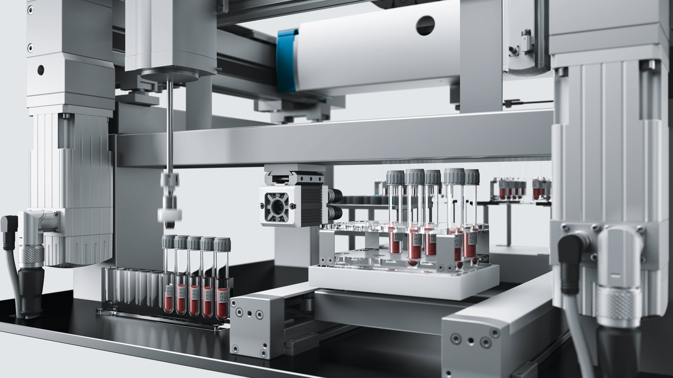
Lab automation is an area where motion control and machine vision work in harmony to produce reliable results
The application in this case study is in the life sciences industry, in a segment commonly referred to as lab automation. The goal of lab automation is to reduce the amount of human labor required to do menial tasks, such as moving samples from one location to another, while increasing the quality of results by minimizing opportunities for human error. Human researchers are the driving force for development in the life sciences industries, but the processes to acquire, analyze, and store large amounts of data are well-suited for automation. Lab automation equipment operates near humans and must be designed with this fact in mind. This means that lab automation equipment should provide clean, safe, and easy access to materials and samples within the machine, and preferably the equipment should operate with minimal levels of audible noise. More than anything, lab automation equipment must be precise and reliable, because the outcome of the scientific studies that result from their use are at stake. By automating menial and tedious tasks for the researchers, the manufacturers of lab automation equipment provide their customers with solutions that free human researchers to focus on the tasks where they excel, such as higher-order thinking and decision-making. Because lab automation equipment doesn’t get tired like human beings, there are fewer errors made and the result of the process is higher quality.
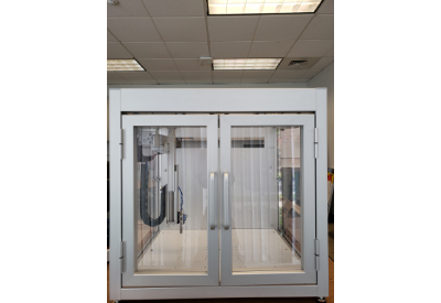
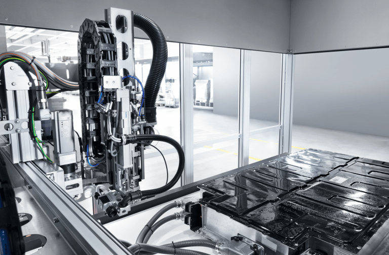
In this application, a lab automation equipment manufacturer wanted to develop a machine to automate the process for centrifuging many samples. The samples are contained in small vials (or test tubes), which are delivered to the input of the machine in trays. From there, the vials are individually picked from the trays and placed into centrifuge baskets by a three-axis handling system (also known as a cartesian robot). The Z-axis of the handling system has two tools attached: a vision system for performing visual inspection of every vial, and an electric gripper module for picking vials one at a time. When the Z-axis is positioned over the top of the tray of vials, the vision system acquires and processes an image of the next vial in the tray to (1) identify the contents of the vial via a code marked on the top of the vial, and (2) to determine the exact position (X-Y coordinates) of the vial in the field of view.
The contents of the vial and its exact position are shared with the machine controller over an Ethernet connection. The machine controller processes the data from the vision system by first forwarding the contents of the vial to an external server that traces the vial through the centrifuge process and ultimately archives the various tests that will be performed on it. The machine controller then uses the exact position coordinates of the vial to command the handling system to an exact pick position directly over the top of the vial. Once a vial is picked, the handling system moves it to, and places it into, a waiting centrifuge basket. Once the centrifuge basket is full, the same handling system picks the basket and moves it to the open centrifuge bay where it places the basket inside the centrifuge.
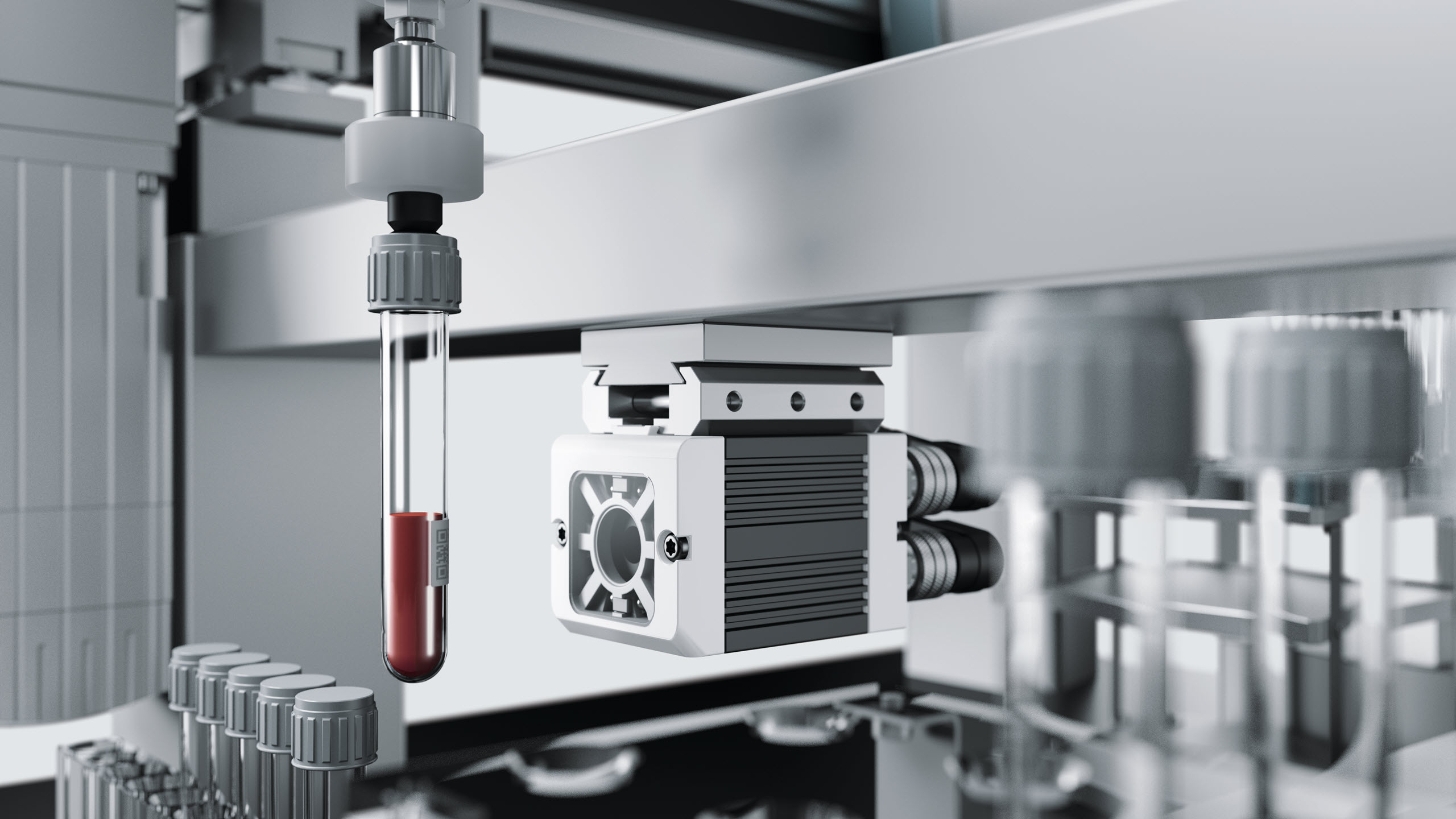
Festo’s years of experience in cartesian handling systems and all aspects of machine control, including machine vision and motion control, was a good fit for the customer. They were able to design a compact, accurate, and robust solution for this application
A second handling system performs a very similar operation, but in reverse of the process described above. This handling system starts working after the centrifuge has spun the baskets for the predetermined time by picking the baskets one by one from the centrifuge, placing the baskets near the output side of the machine, and then one by one picking individual vials from the baskets and placing them into empty trays. A second vision system on this handling system performs a similar vision inspection of each vial, sending the contents and position data to the same machine controller as the first handling system.
Of note in this application is that a single machine controller is used to process the image results from the vision systems and to command the motion of the handling systems. This is one area in which designing for both machine vision and motion control at the same time provides benefits to the end user. The single machine controller saves cost and space over separate, dedicated controllers, while saving programming and maintenance time by allowing the operator to manage all machine code in a single controller.
The Customer Faced Some Challenges
The primary challenge faced in this application is that the lab lacked in-house expertise to design and build a machine to perform the tasks discussed above. The customer had expertise in research and diagnostics of fluid samples and was able to define a clear requirement for the process, but was less able to design a machine to replicate the tasks carried out by a human operator.
The Solution: Two Multi-Axis Motion Control Systems, Two Smart Camera Vision Systems, A SIngle Controller and A Lot of Know-How from Festo
The function of the two multi-axis motion control systems, or handling systems, in this application is to replicate what a human would do in the tedious task of moving samples into and out of a centrifuge. A typical research process requires as many as 300 samples to be tested per hour. In each process the contents of every sample must be documented on the server before being placed inside the centrifuge. After the centrifuge completes its cycle, each sample must be unloaded from the centrifuge and positioned for the next step in the research or diagnostic procedure. The entire process of documenting sample contents and loading and unloading vials from the centrifuge is tedious, but not trivial. It is tedious because of the large number of samples, but not trivial because it requires accuracy and gentle handling of the glass vials.
A precision handling system is an ideal solution to replace this tedious task because it can perform repetitive tasks without fail and is accurate enough to gently handle the vials in a similar way to how a human would do so. Festo offers point-to-point and interpolated motion control solutions for one, two, or three axes. Point-to-point motion control for additional axes, such as rotary axes, can be easily added. A strength of Festo is handling systems comprised of multiple axes and a common application is pick-and-place. When building multi-axis handling systems, system accuracy, cable management, and system rigidity are key considerations. Festo adequately covers all these aspects in the design of handling systems.
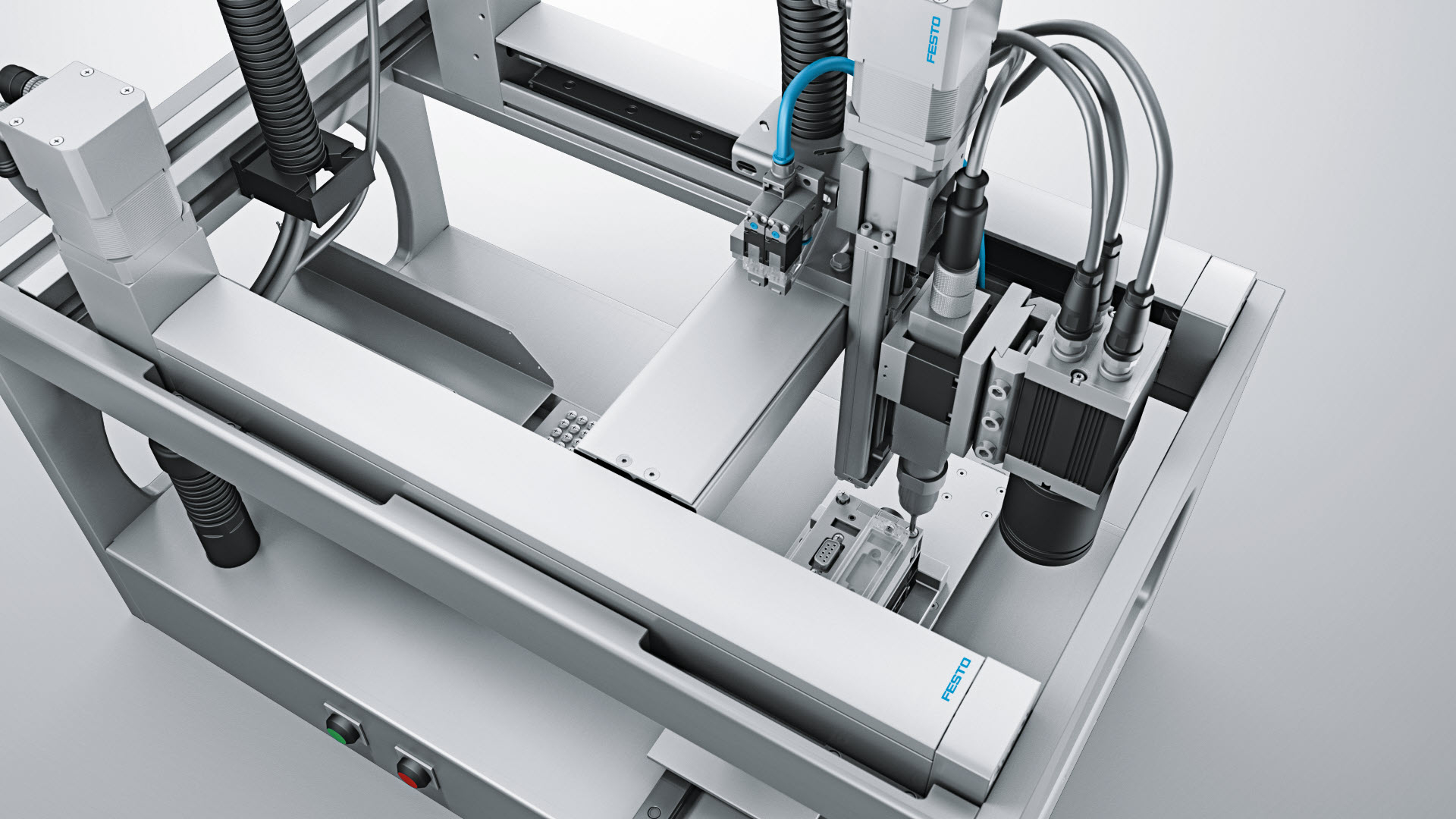
A three-axis handling system, also known as a cartesian robot, for movement in a 3D workspace. A ready-to-install, complete system, including energy supply and suitable motor and motor controller package
Festo’s years of experience in cartesian handling systems and all aspects of machine control, including machine vision and motion control, was a good fit for the customer. The customer was able to rely on a close collaboration with the engineering team at Festo, which married the specific requirements of the centrifuge process with the skillset to design a compact, accurate, and robust solution for the application.
Festo excels in multi-axis handling systems and cartesian robots and their handling systems are powered by precision servo motors and drives and sophisticated controllers that provide machine designers with a powerful and comprehensive tool set for solving applications like this. These tools were developed by Festo based on many years of experience in multi-axis handling systems.
The function of the machine vision system in this application is to replicate the visual inspection tasks of the human operator. This includes accurately identifying the contents of every vial and accurately providing the exact position of every vial to the motion control algorithm inside the controller. Unlike a human operator the vision system never gets tired, even after processing hundreds of vials per hour. This level of reliable performance from the vision system reduces human error and enables the automation of a complicated process. Smart cameras are a common solution in machine vision applications. Festo’s machine vision system offering consists of smart cameras available in either a fully integrated camera with on-board lens and lighting or a C-mount camera for use with external lens and lighting. The product range covers a wide range of common machine vision tasks including code reading, feature identification, object detection, measurement, counting, sorting, and robotic guidance.
The vision system used in this application is a smart camera from Festo, which includes all elements of the vision system in a single device: illumination of each vial via on-board LEDs, an integrated lens and sensor to capture the image of each vial in the field of view, and on-board processing to analyze the digital image and provide the necessary results to the machine controller. The benefit of a Festo smart camera in this application is the easy integration of the camera into the Festo machine controller. Festo provided reusable function blocks for controlling their cameras and handling systems. These function blocks streamlined the development of the machine code while enabling rapid development of turn-key solutions.
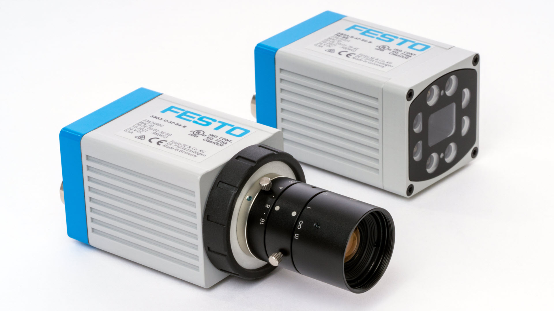
Festo’s machine vision system offering consists of smart cameras available in either a fully integrated camera with on-board lens and lighting or a C-mount camera for use with external lens and lighting. The product range covers a wide range of common machine vision tasks including code reading, feature identification, object detection, measurement, counting, sorting, and robotic guidance
One critical aspect of marrying motion control and machine vision is to calibrate the coordinates of both systems to each other. The position of objects in the camera’s field of view must translate accurately to the coordinate system used by the handling system. The camera’s native units are pixels while the handling system’s native units are the encoder counts of the servo motors driving the axes. The translation from pixels to encoder counts is not trivial. The position of the camera relative to the object(s) in its field of view must be consistent and repeatable over time.
One common solution is to mount the camera in a fixed position over the workspace of the machine, so that that the camera can see all objects in its field of view. This provides a very rigid reference point for the camera’s position in the machine, but in this application, it would not have been feasible because of the large workspace and the large number of vials. Instead, the camera was mounted to the Z-axis of the handling system and moved with the Z-axis to every pick position. The benefit of this approach is that the camera can be positioned to view one vial at a time. This greatly increases the resolution of a single vial in every image the camera takes and increases the amount of position information the camera can extract from the image. When the camera is mounted to the handling system like this it means the handling system must have high repeatability as it moves between the dozens of different positions within the machine.
In the case of a three-axis handling system (X-Y-Z) the requirement for high repeatability is more acute because any inaccuracies in one axis will compound inaccuracies in the other axes. The primary solution to this challenge is to use precision actuators and servo motors as the basis for the handling system combined with many years of experience in building sophisticated, multi-axis handling systems.
As stated earlier, a benefit of the single machine controller approach to this application is that all machine code can be maintained and managed through one interface. Festo motion controllers are built upon CODESYS, the industrial programming environment for IEC 61131-3 compliant coding, and their servo drives are designed for control over standard industrial Ethernet protocols such as EtherCAT, PROFINET, EtherNet/IP, and Modbus.
Controlling the motion and vision systems can be dauting, but the customer is not on their own once the machine design is complete. In addition to the local Festo engineering team that worked with the customer throughout the machine design process, Festo employs more than 20,000 sales, support, and technical personnel in over 60 countries around the world. Wherever the customer’s machines may end up, local service and support resources are available.
Support From Start to Finish – and Beyond
The benefits provided by Festo to its customer in this application include a collaborative engineering approach from beginning to end in the design project, a deep expertise in handling systems, and a comprehensive approach to integrating key machine functions like motion control and machine vision in the final solution. The engineering team at Festo consists of mechanical, electrical, and computer engineering experts who engage with machine builders and solution providers around the world to solve challenging automation tasks.
With respect to the vision system in this application, samples of the vials were first provided to Festo so that a preliminary evaluation of the visual inspection tasks could be performed by Festo engineers. Then, a smart camera with integrated lighting solution was chosen as the vision system. Critically, at the earliest stages of this project, Festo engineers also considered the precision handling requirements of the machine. This dictated that the smart camera be able to provide accurate X-Y coordinate data to the motion controller, and therefore a smart camera with coordinate calibration features was selected. Coordinate calibration between the position of vials inside the camera’s field of view and the real-world coordinates of the cartesian robot was essential for this application to be successful.
By considering these requirements early in the process, Festo engineers were able to provide additional benefits to the customer in terms of reduced design time and lower total cost for the solution. This is another example of the synergy possible when designing for machine vision and motion control at the same time. Festo offers support whenever you need them, online or in person. This applies to all phases, from engineering to operation and beyond. They listen to you and help you to keep your processes running optimally and without downtimes. When it matters most, they provide help quickly. To see their service and support at any phase, click here.
Interested in learning more? Visit Festo today

