Connectivity Corner: The As and Bs of IO-Link

October 7, 2021
By Colin Cartwright, System Sales Manager, MURR CANADA
Now we’re all back from our summer breaks, it’s time to get back to work and continue our Connectivity Corner series. Last time out, we looked at the similarities IO-Link has with USB in “Why IO-Link is Like an Industrial Version of USB”.
Over the next couple of months, we’re going to dig deeper into some of the technical aspects of IO-Link so you can have a better understanding of the data types, communication speeds, maximum transmission distance, and the different power classes of IO-Link.
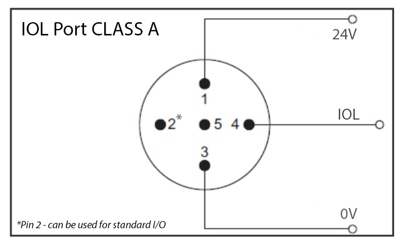
Let’s start with the connection pin-outs you’ll typically find on an IO-Link device. With most IO-Link devices coming with M12 connectors, we’ll use the pin-out configuration of an M12 connector for our examples. The most basic version of IO-Link only requires three connections to be made: Pin 1 = 24VDC, Pin 3 = 0V, and Pin 4 = IO-Link Communication. Yes, pins 1,3, and 4 are the same pins you would usually use to connect regular sensors. Uniformity is one of the nice things about the IO-Link standard. An IO-Link device requiring only these three connections is categorized as a Class A device.
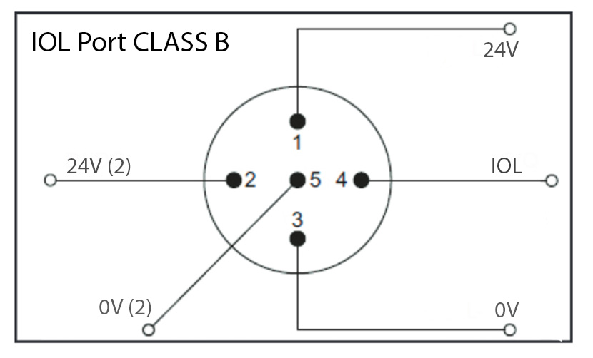
Some IO-Link devices (usually output devices like valve manifolds) need additional power so for these devices you will also need to connect Pin 2 to 24VDC and Pin 5 to 0V. You can either use the same power supply or a different power supply for these connections. If your IO-Link device requires all five pins to be connected, then it is categorized as a Class B device.
So other than an extra two wires to connect, what’s the real difference between Class A and Class B?
Well, it basically comes down to the amount of current available on pin 1. The IO-Link standard (IEC 61131-9) specifies that the maximum current for Class A devices should be 200mA. That’s plenty of power for input devices like proximity sensors or cylinder reed switches, but it’s a little low to drive a hydraulic solenoid or a valve bank with 16 valves. The Class B standard was therefore introduced to provide extra power for these types of IO-Link devices. There is no current limit specified for Class B devices in the IO-Link standard, but as the individual pins of M12 connectors are limited to 2A, the maximum amount of current that can be supplied to a Class B IO-Link device is typically 2A.
One major benefit of IO-Link Class B connectivity is the potential to connect output devices to safety systems. Using a special T-Coupler will enable you to connect the actuator power separately to the IO-Link power. For example, pins 2 and 5 can be connected to a safety relay or safety controller which will enable you to shut down the actuator power without affecting the communication to the device.
Here is an example showing a Murrelektronik Cube67 IO-Link Module controlling a Festo valve bank with an IO-Link interface using one of our IO-Link T-Couplers to separate the actuator power.
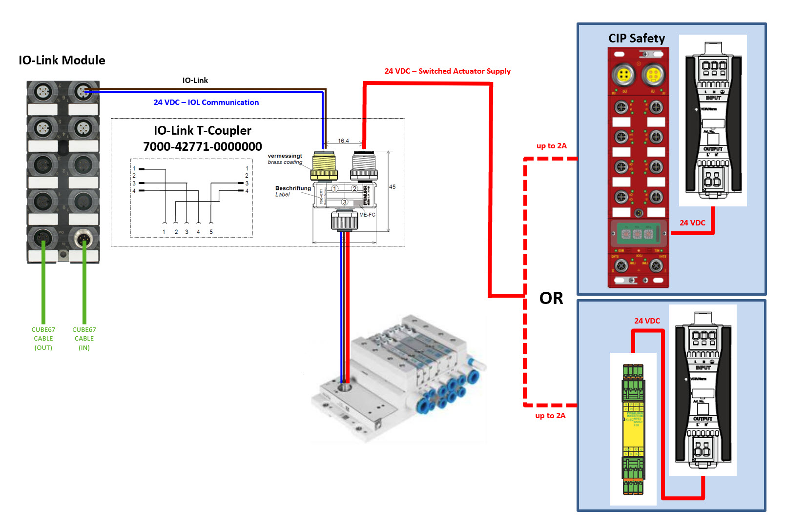
In this example, an M12 IO-Link port on the IO-Link module provides basic power and IO-Link communication to the valve bank via pins 1,3 and 4 on the left side of the T-Coupler, while the power for the valve solenoids is supplied separately from a safety relay or safety I/O module connected to pins 2 and 5 on the right side of the T-coupler. When the safety outputs feeding the switched actuator supply are turned off there will be no power to pin 2 on the valve bank connector to energize the valve solenoids so they cannot move, however, IO-Link communication is still enabled.
With many pneumatic manufacturers now offering IO-Link interfaces for their valve banks, I think this is now the most economical and effective way to connect valve banks. It reduces your electrical connection to a single 5-pole M12 cable and enables you to locate a valve bank anywhere there is an I/O module with IO-Link Class B ports, rather than running a cable back to your panel or adding an additional IP address.
That’s it for this month. Next month we’ll be digging deeper into the technical side of IO-Link data types and communication speeds. Have a great month!